Background
The client makes two types of systems, a manual stand alone system and an inline system. Both systems use a powerful image processing system to check the various label properties.
The inline system becomes part of the end users production line and uses a system of multiple cameras, conveyors and reject mechanisms to inspect and control the flow of products through the system. Traditionally the system used a PLC to control the inspection systems and communicate with the other systems on the line.
With all the various options available on the system the PLC code had become very complex and was becoming difficult to maintain especially as new systems required more and different functionality. The current PLC had reached the limitations of its capabilities and an alternative was required.
Requirements
The hardware specification was reasonably loose but there where a number of important requirements.
Hardware:
- All I/O needs to be optically isolated.
- Output to be a mixture of PNP 24V 2A and solid state relays.
- A 24V Quadrature encoder input.
- Removable and re-wirable connectors, played out in a logical way.
- USB and RS232 interfaces.
- Remotely upgradable firmware.
- Small footprint.
- LEDs on all I/O.
- Onboard configuration storage.
- A 0-10V analogue output (does not need to be isolated).
- Two 24V PWM outputs.
- Expandable.
- Flexible enough for sale on the open market.
- Low cost.
- To include a small batch of boards for testing/development.
Software:
- To prove the functionality of the board.
- To communicate with the PC via the RS232 and/or USB port.
- To provide camera triggers based on the encoder and input trigger.
- A basic PC based configuration and test utility.
- A set of library calls to configure and use all the board peripherals.
- To be remotely upgradable.
Design
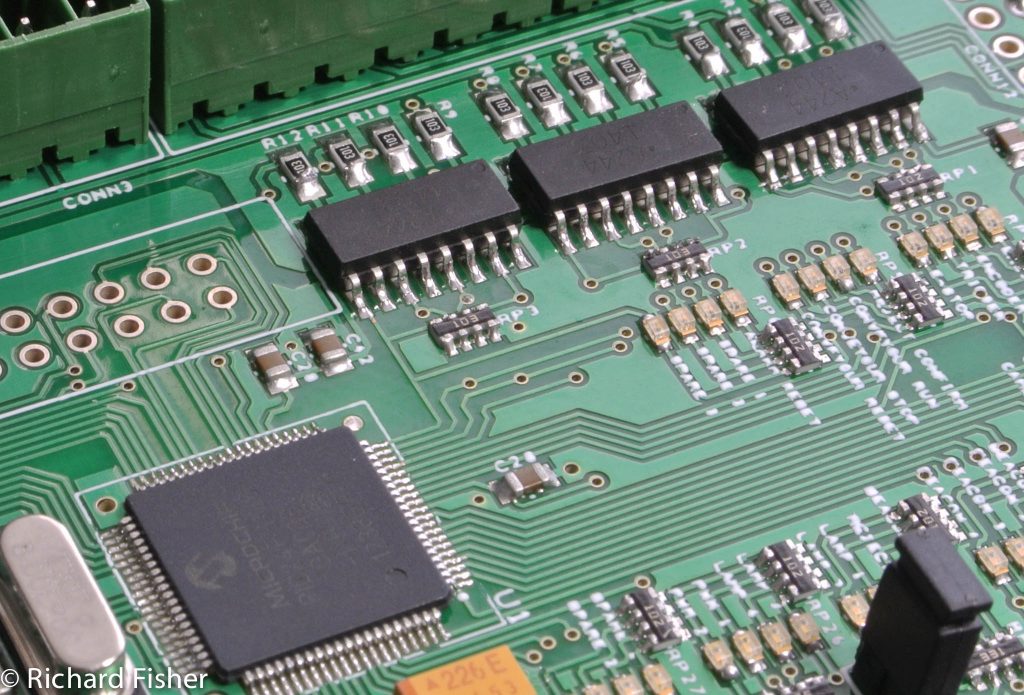
A suitable microcontroller was chosen, a 16 bit PIC24 from Microchip. This device has multiple coms ports, SPI, I2C along with enough I/O for the required functions. Next on the list were the various interface connectors, due to the requirements these turned out to be one of the most costly parts as well as the largest. Suitable output drivers were chosen along with OPTO coupled devices that could handle the high frequency of the encoder and PWM outputs.
The circuit was designed and along with a few other parts the board was ready to be designed. The various connectors and required layout dictated the overall size of the board, it was a little larger than the original spec but convenience of installation and maintenance was chosen over size (it was still smaller than the existing PLC/Distribution board option).
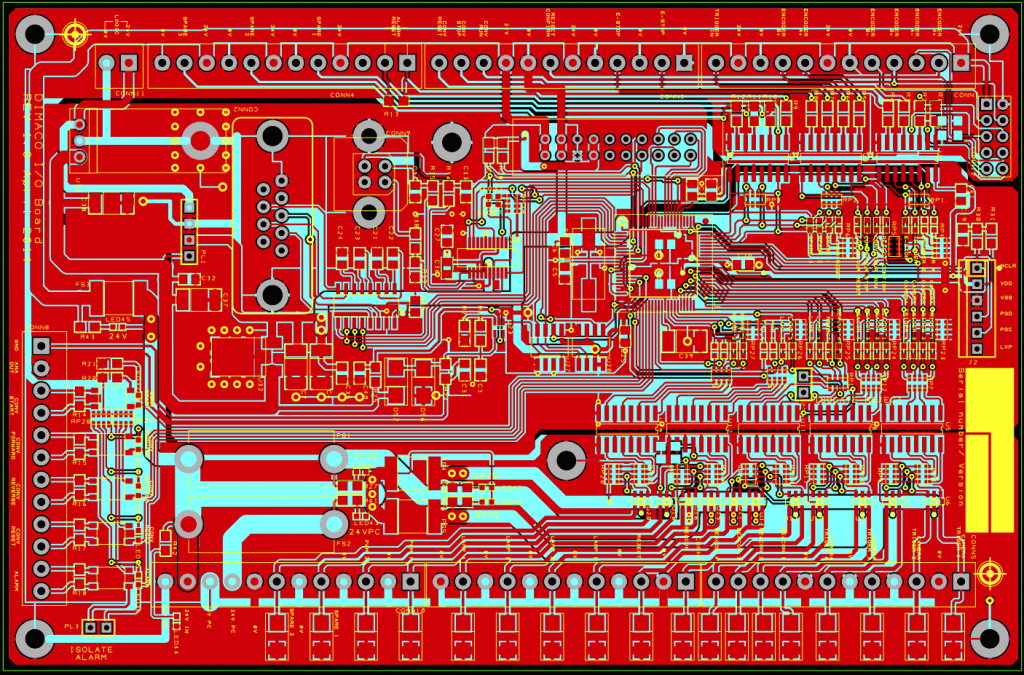
The build was approved by the client.
Build
Due to the time taken to produce PCBs at a sensible cost the decision was made to produce all the boards at once instead of an initial prototype and then the small production. One of the boards was used to produce the prototype, write the software and prove. This was done, and with the exception of a couple of resistor values on the high speed signals all worked first time – yay!
The rest of the boards were populated, tested and delivered to the client.
Software

MPLABX was used to write the software. As the client wanted to further develop the firmware themselves the cost of the development environment is important. Microchip offer MPLAB at various levels, the first being free! The various paid levels introduce better optimisation levels, I’ve never needed to use anything but the basic package.
The software was written to the required specification. When idle the loop time was 63.5 micro-seconds, this increased by around 50% when working and tracking parts through the system. The original PLC had a cycle time of several milli-seconds so this is a significant improvement.
Result
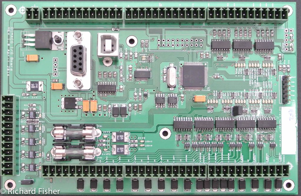
With the exception of a small footprint all the requirements where met. Despite using surface mount components where possible the board was larger than I hoped, this was largely due to the connectors used and to maintain a sensible LED layout.
The prototype was fitted to the test machine and with the exception of a couple of inverted inputs and outputs worked OK.
A number of prototypes were manufactured and shipped to the client, they are now integrating it fully into there system, both hardware and software.
The next step is to have the boards manufactured by a PCB assembly company.